As one of the power supply components, the role of capacitors is no more than the following.
1. Applied to power supply circuits to achieve bypass. Decoupling. The role of filtering and energy storage.
The following categories are listed below.
1) Bypass
A capacitor that can bypass the high-frequency components in the communication between high-frequency current and low-frequency current is called “bypass capacitor”. For the same circuit, the bypass capacitor is to filter out the high frequency noise in the input signal, and to filter out the high frequency noise carried by the front stage, while the decoupling capacitor is to filter out the disturbance of the output signal. The primary function of the bypass capacitor is to produce a communication split, and then eliminate the unwanted energy that enters the susceptible area, that is, when the signal mixed with high and low frequencies is expanded through the amplifier, it is required to pass through a certain level when only the low frequency signal is allowed to be input to the next level, and no high frequency signal is needed to enter, then a proper size ground capacitor is added at the input of the level, so that the higher frequency signal can easily pass through this capacitor is bypassed off (this is due to the small impedance of the capacitor to the high frequency), while the low frequency signal is delivered to the next level for expansion due to the larger impedance of the capacitor to it. The bypass capacitor is an energy storage device that supplies energy to the local device, which homogenizes the output of the regulator and reduces the load demand. Like a small rechargeable battery, the bypass capacitor can be charged,amperometric capacitors, and discharged to the device.
The bypass capacitor can be charged and discharged to the device. In order to minimize impedance, the bypass capacitor should be as close as possible to the power supply pin and ground pin of the load device. This can be a good way to avoid the low power lift and noise caused by too large an input value. Ground bounce is the voltage drop in the ground connection when passing through a high current burr.
2)De-coupling
De-coupling, also known as uncoupling. In terms of the circuit, it is always possible to distinguish between the source of the drive and the load of the drive. Assuming that the load capacitance is relatively large, the driver circuit has to charge and discharge the capacitor to end the signal jump, and the current is relatively large when the rising edge is relatively steep, so that the driver’s power supply will absorb a large supply current, due to the inductance in the circuit, the resistance (especially the inductance on the chip pin, which will produce a bounce), this current is related to the normal condition in practice is a noise, which will affect the front stage This is the so-called “coupling”. The decoupling capacitor is to play the role of a “battery” to satisfy the current change of the driver circuit and avoid the coupling annoyance between them. Combining bypass capacitor and decoupling capacitor will be easier to understand. Bypass capacitors are also de-coupled in practice, but bypass capacitors generally refer to high-frequency bypass, that is, to give high-frequency switching noise high a low-impedance drain path. The high frequency bypass capacitor is generally small, taking 0.1uF etc. according to the resonant frequency; while the capacity of the de-coupling capacitor is larger, maybe 10uF or perhaps larger, according to the distribution parameters in the circuit, and the size of the drive current change to admit. The bypass is to take the annoyance in the input signal as the filtering policy, while the decoupling is to take the annoyance in the output signal as the filtering policy to avoid the annoyance signal to return to the power supply. This should be the essential difference between them. On the one hand, it is the storage capacitance of the integrated circuit, and on the other hand, it bypasses off the high frequency noise of the device. The typical value of decoupling capacitor in digital circuits is 0.1u. The typical value of distributed inductance of this capacitor is 5nH,ceramic capacitor.
A 0.1uF decoupling capacitor has a distributed inductance of 5nH, and its parallel zone vibration frequency is about 7MHz, which means that it has a good decoupling effect on noise below 10MHz and almost no effect on noise above 40MHz. 1Uf, 10uf capacitor, with a parallel resonance frequency above 20MHz, has a better effect of removing high frequency noise. Every 10 or so ICs should add a charge/discharge capacitor, or an accumulator capacitor, which can be chosen around 10uF. No need to electrolytic capacitor, electrolytic capacitor is two layers of film rolled up, this rolled up structure behaves as inductance in high frequency. To use tantalum capacitor or polycarbonate capacitor. The selection of decoupling capacitor is not strict, it can be taken as C=1/F, i.e. 0.1uf for 10MHz and 0.01uF for 100MHz.
3) Filtering
Theoretically (i.e. assuming the capacitor is pure), the larger the capacitor, the smaller the resistance, and the higher the frequency. But in practice, most of the capacitors over 1UF are electrolytic capacitors, which have a large inductive component, so the impedance will increase after the frequency is high. Sometimes you can see a large capacitance electrolytic capacitor in parallel with a small capacitor, when the large capacitor through the low frequency, small capacitor through the high frequency. The role of capacitance is to pass high resistance low, through high frequency resistance low frequency. The larger the capacitance, the simpler the low frequency, the smaller the capacitance, the simpler the high frequency. Specifically used in filtering, large capacitors (1000UF) filter low frequency, small capacitors (20PF) filter high frequency. Some users have imaginatively compared the filtering capacitor to a “water pond”. Since the voltage at both ends of the capacitor does not change suddenly, it can be seen that the higher the frequency of the signal, the greater the attenuation. It converts the change of voltage into the change of current, the higher the frequency, the higher the X2 amperometric capacitor
The higher the frequency, the higher the peak current, and then the voltage is buffered. Filtering is the process of charging, discharging.
4) Energy storage
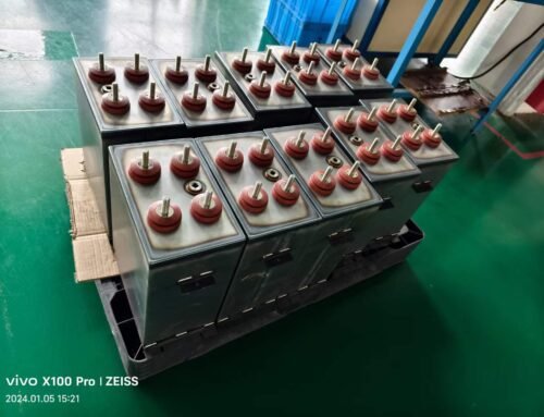
The energy storage capacitor collects charge through the rectifier and transfers the stored energy to the output of the power supply through the converter leads. The voltage rating is 40-450VDC . Aluminum electrolytic capacitors with capacitance values between 220-150000UF are more commonly used. According to different power requirements, the devices are sometimes connected in series, parallel or a combination thereof. For power supplies with power levels over 10KV, the larger can-shaped screw terminal capacitors are generally used.

200F 2.7V Суперконденсатор 16V


